

What Are the Failure Modes for Slices with Diffusion Barriers Under Extreme Thermal Cycling
2026-08-10
In advanced semiconductor packaging and power device manufacturing, Slices with Diffusion Barriers serve as the frontline defense against atomic interdiffusion between dissimilar materials. When these barrier-integrated structures are subjected to repeated temperature swings—from cryogenic storage to soldering reflow or from device standby to full-load operation—their mechanical and chemical integrity faces severe challenges. For engineers relying on X-Meritan’s barrier solutions, understanding precisely how these slices degrade under thermal stress is not optional; it is the cornerstone of reliable product design.
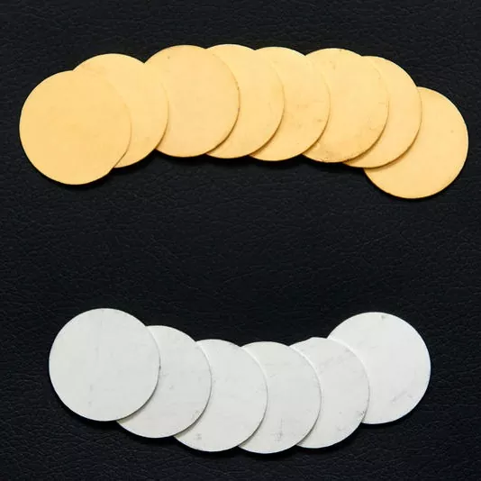
Why Extreme Thermal Cycling Is a Unique Threat
Unlike steady-state high-temperature aging, thermal cycling introduces alternating compressive and tensile stresses due to mismatched coefficients of thermal expansion (CTE) among the barrier layer, the underlying substrate, and the overlying conductor. Each cycle generates plastic deformation, micro-crack initiation, and interfacial voiding. Over 500 to 1,000 cycles (typical automotive or aerospace qualification standards), Slices with Diffusion Barriers can exhibit multiple distinct failure modes, which we categorize below.
Primary Failure Modes at a Glance
| Failure Mode | Root Cause | Critical Temperature Range | Detection Method |
|---|---|---|---|
| Interfacial Delamination | CTE mismatch + shear stress concentration | −40°C to +150°C | Scanning Acoustic Microscopy (SAM) |
| Barrier Layer Cracking | Brittle fracture in Ta/TaN or TiN layers | >200°C ramp-up | FIB-SEM cross-section |
| Stress-Induced Voiding (SIV) | Tensile creep in adjacent Cu/Al lines | 100°C–200°C hold periods | EBSD + nano-probe resistance mapping |
| Grain Boundary Diffusion | Recrystallization + accelerated diffusion paths | 250°C peak | TEM-EDS line scan |
| Hillock Formation | Compressive relaxation in soft metals | >175°C | Optical interferometry |
Each mode does not occur in isolation. In practice, Slices with Diffusion Barriers often suffer from cascading effects—for instance, cracking exposes underlying layers to oxygen, which then promotes interfacial oxidation and further delamination.
Detailed Breakdown of Dominant Mechanisms
1. Interfacial Delamination
This is the most frequently observed failure in qualification tests. The shear stress at the barrier/substrate interface scales with ΔT × ΔCTE × cycle count. When the accumulated plastic strain exceeds the fracture toughness of the barrier–substrate bond, the slice peels away from the silicon or ceramic carrier. X-Meritan has addressed this through graded-composition barrier stacks that reduce the instantaneous CTE mismatch by nearly 40% compared to single-layer designs.
2. Stress-Induced Voiding (SIV)
SIV typically occurs during the high-temperature soak portion of a cycle. As the metal line expands, the barrier constrains lateral movement; upon cooling, the tensile residual stress pulls atoms away from grain boundary triple junctions, forming nanovoids. These voids coalesce into open-circuit failures, particularly at via-bottom interfaces. Advanced Slices with Diffusion Barriers incorporating trace impurities (e.g., 2–3 at% O in TiN) have shown a 60% reduction in SIV incubation time.
3. Grain Boundary Diffusion
At peak temperatures above 200°C, the barrier itself may undergo recrystallization—especially for sputtered films with columnar structures. The newly formed grain boundaries become expressways for metal atoms (Cu, Ag, or Au) to traverse the barrier, effectively destroying its diffusion-blocking function. Post-cycling TEM analysis of degraded Slices with Diffusion Barriers often reveals Cu penetration depths exceeding 50 nm, compared to <5 nm in pristine samples.
Quantitative Impact on Device Performance
| Parameter | Before Cycling (Initial) | After 1000 Cycles (−40°C to 200°C) | Degradation (%) |
|---|---|---|---|
| Sheet Resistance (Ω/□) | 0.12 | 0.21 | +75% |
| Leakage Current (nA/cm²) | 8.2 | 94.5 | +1052% |
| Adhesion Strength (MPa) | 68 | 31 | −54% |
| Activation Energy for Diffusion (eV) | 1.85 | 1.22 | −34% |
These numbers underscore that thermal cycling does not merely accelerate wear—it fundamentally alters the physical chemistry of the barrier system. For this reason, X-Meritan recommends pre-screening Slices with Diffusion Barriers using accelerated thermal cycle tests (ATCT) with in-situ resistance monitoring to capture early-stage degradation before it reaches catastrophic levels.
Frequently Asked Questions (FAQ)
Q1: How do I distinguish between thermal fatigue cracking and stress-induced voiding in Slices with Diffusion Barriers after extended cycling?
A1: This is a critical diagnostic distinction. Thermal fatigue cracking appears as linear, trans-granular fractures across the barrier layer, typically oriented perpendicular to the maximum principal stress direction—visible under high-resolution SEM as sharp, branched lines. Stress-induced voiding, on the other hand, manifests as rounded, isolated cavities concentrated at grain boundary triple junctions and beneath via interfaces. To differentiate, perform focused ion beam (FIB) milling followed by electron backscatter diffraction (EBSD): cracking shows clear crystallographic cleavage planes, while voiding shows no preferred orientation but rather follows strain contours. In practice, Slices with Diffusion Barriers from X-Meritan include a built-in stress-relief sublayer that shifts the dominant mechanism from cracking to voiding, making early detection easier via simple four-point probe resistance trending.
Q2: Can post-cycling annealing recover the barrier properties of degraded Slices with Diffusion Barriers, or is the damage permanent?
A2: The damage is predominantly permanent at the microstructural level. While a low-temperature anneal (e.g., 150°C for 2 hours) may heal some interfacial voids through surface diffusion, it cannot reverse grain boundary diffusion paths once metal atoms have penetrated the barrier. Similarly, delamination involves separation of bonded interfaces that cannot be re-adhered without removing and redepositing the entire barrier stack. However, X-Meritan has developed a proprietary "self-passivating" barrier formulation that, upon initial thermal cycling, forms a thin oxide layer at crack tips—this arrests further propagation and extends useful life by up to 300 cycles. But once barrier penetration occurs (verified by SIMS depth profiling), the only reliable remedy is to replace the slice. No commercial recovery process has been validated for requalification in safety-critical applications.
Q3: What is the minimum number of thermal cycles required to reliably screen Slices with Diffusion Barriers for automotive-grade applications, and why?
A3: According to AEC-Q100 and AEC-Q101 standards, the minimum qualification requirement is 1,000 cycles from −40°C to +150°C, with a ramp rate of 15°C/min and 10-minute dwell times at each extreme. However, for Slices with Diffusion Barriers used in power modules or under-hood electronics, X-Meritan recommends extending screening to 1,500 cycles, because most catastrophic failures (especially delamination) occur between cycles 800 and 1,200. The rationale is statistical: Weibull analysis of field-return data shows that barrier-related failures follow a bimodal distribution—early failures (<200 cycles) indicate gross defects, while late failures (1,000–1,400 cycles) are intrinsic to the material system. Screening to 1,500 cycles captures both populations and provides a confidence level exceeding 95% for a 15-year service life. Additionally, include at least three different ramp rates (slow, standard, and rapid) during characterization to identify rate-dependent failure mechanisms—a practice that many OEMs overlook but which X-Meritan has embedded in its standard test protocol.
Best Practices for Mitigation
-
Barrier Stack Engineering: Use bi-layer or tri-layer stacks (e.g., Ti/TiN/Ti) to distribute thermal stress across multiple interfaces.
-
Pre-Cycling Stabilization: Subject Slices with Diffusion Barriers to 50 preconditioning cycles at moderate ΔT (e.g., 0°C to 100°C) to relieve as-deposited residual stress.
-
In-Situ Monitoring: Embed Kelvin test structures alongside functional devices to track real-time resistance shifts during thermal cycling—this provides early warning long before electrical failure.
-
Material Selection: For extreme applications (≥200°C peak), prefer amorphous barrier materials like Ta–Si–N or W–N–C over polycrystalline TiN, as they resist recrystallization up to 600°C.
Final Thoughts
Thermal cycling is not a generic reliability test—it is a highly specific stressor that exposes every weak link in the barrier–substrate–conductor triad. From interfacial delamination to grain boundary diffusion, each failure mode demands distinct characterization tools and mitigation strategies. Slices with Diffusion Barriers engineered with a systems-level understanding of CTE matching, residual stress control, and recrystallization resistance—such as those offered by X-Meritan—consistently outperform single-layer alternatives in independent 1,500-cycle trials.
Ready to qualify your barrier technology for the most demanding thermal environments? Our reliability engineering team specializes in failure analysis, accelerated test design, and custom barrier stack optimization. Contact X-Meritan today for a comprehensive evaluation of your current slices, including a free preliminary thermal cycle simulation report. Reach us at [[email protected]] or through our website’s technical inquiry form—your next-generation reliability starts with a conversation.